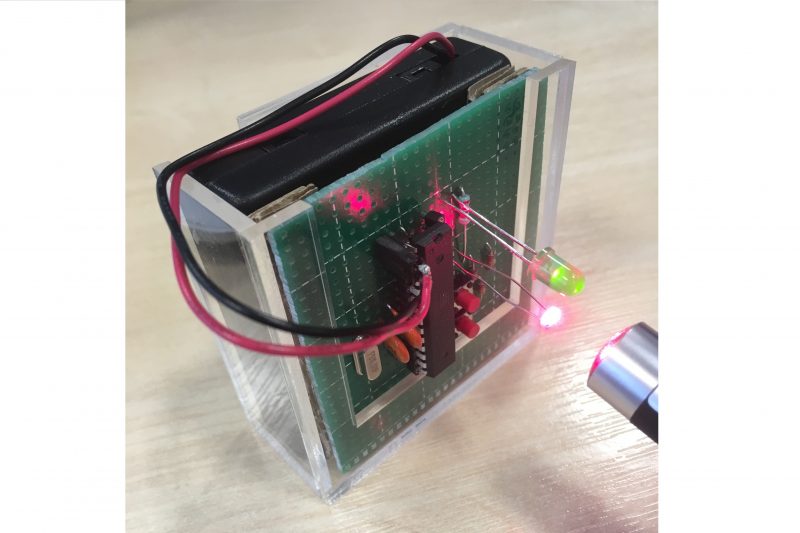
Arduino circuit to demonstrate scattering of light
This Light Up Arduino helps students understand what scattering of light is and how it works. A laser pen is used to shine light onto the photoresistor, and when the light intensity reaching the photoresistor exceeds a certain threshold, the greed LED lights up. This setup is used with water-filled cuvettes, where students can use a pipette to drip drops of milk into the cuvettes to see the decrease in intensity of laser light reaching the photoresistor when shining the beam though the water-milk mixture. Students can count how many droplets of milk it takes to decrease the intensity to not trigger the LED, and finally calculate the milk concentration needed for such a phenomenon.
Let’s start with the Arduino!
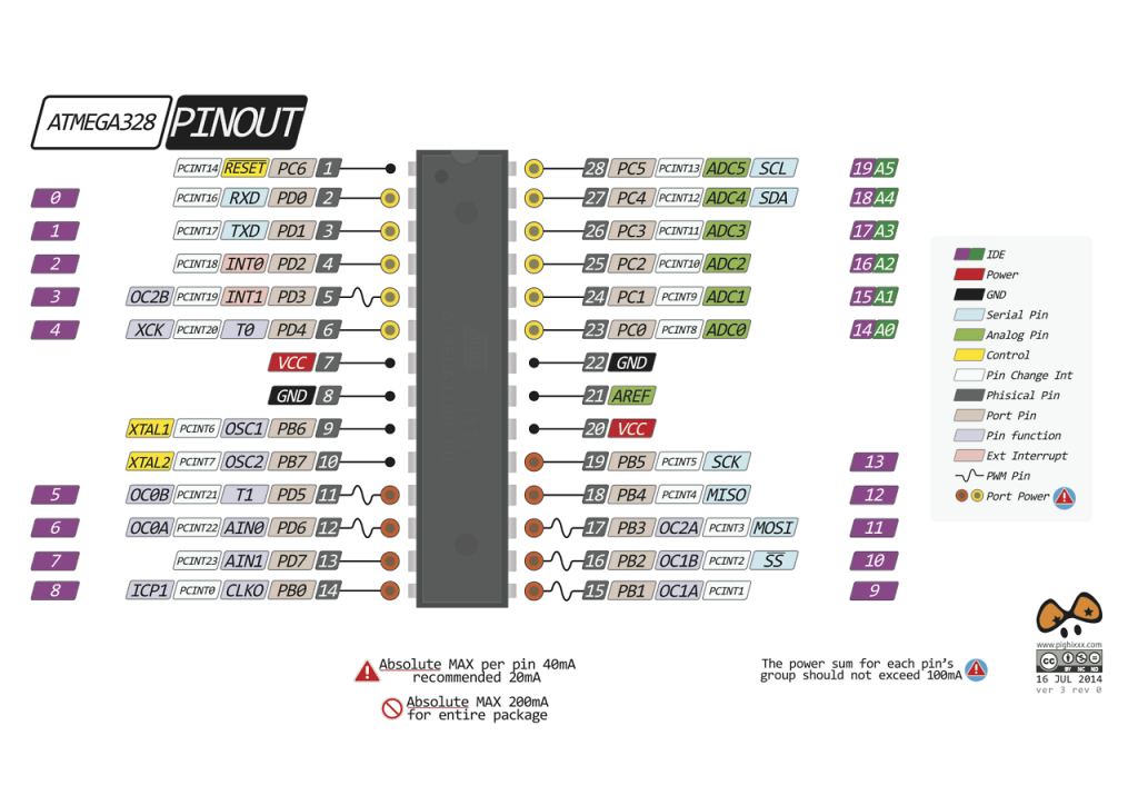
The Arduino ATMEGA328 can be coded with an Arduino by plugging into the relative pins, and runs on 4 AA batteries when not connected to an Arduino breakout board. Make sure it is connected in the correct orientation, or it will not work! The ATMEGA328 pinout is according to the diagram below (courtesy of https://www.pighixxx.net/):
The code is as follows:
/*
* 20180212
* Photoresistor to demonstrate light scattering from laser
* MetaboLight – Nico Chen
*/
//assign pin numbers
const int greenLEDPin = A5;
const int upButtonPin = 12;
const int upButtonVoltage = 13;
const int downButtonPin = 9;
const int downButtonVoltage = 11;
const int photoresistorPin = A1;
const int photoresistorVoltage = A0;
int upButtonState = 0;
int prevUpButtonState = 0;
int upButtonEnabled = 0;
int downButtonState = 0;
int prevDownButtonState = 0;
int downButtonEnabled = 0;
int sensorValue;
int lightUpValue = 950; //set threshold
void setup() {
pinMode(greenLEDPin, OUTPUT);
digitalWrite(greenLEDPin, LOW);
pinMode(photoresistorVoltage, OUTPUT);
digitalWrite(photoresistorVoltage, HIGH);
pinMode(upButtonVoltage, OUTPUT);
digitalWrite(upButtonVoltage, HIGH);
pinMode(downButtonVoltage, OUTPUT);
digitalWrite(downButtonVoltage, HIGH);
Serial.begin(9600);
}
void loop() {
sensorValue = analogRead(photoresistorPin);
if(sensorValue >= lightUpValue){
digitalWrite(greenLEDPin, HIGH); //set LED to light up when intensity is larger than threshold
}
else{
digitalWrite(greenLEDPin, LOW);
}
upButtonState = digitalRead(upButtonPin);
if(upButtonState != prevUpButtonState && upButtonState == HIGH){
lightUpValue = lightUpValue+10; //increase threshold by 10 whenever up button is pressed
}
prevUpButtonState = upButtonState;
downButtonState = digitalRead(downButtonPin);
if(downButtonState != prevDownButtonState && downButtonState == HIGH){
lightUpValue = lightUpValue-10; //decrease threshold by 10 whenever down button is pressed
}
prevDownButtonState = downButtonState;
Serial.print(lightUpValue);
Serial.print(” “);
Serial.println(sensorValue);
}
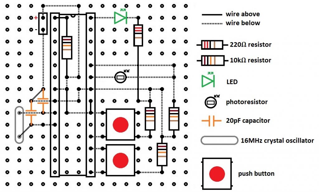
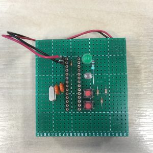
Once the code is uploaded, a bit of soldering is required. The diagrams above show how the board should be soldered.
Here’s a list of what you will need:
1 x ATMEGA328
1 x Perfboard
4 x AA battery
1 x battery case
1 x 16MHz crystal oscillator
2 x 20pF capacitor
1 x green LED
1 x photoresistor
2 x push button
1 x 200Ω resistor
3 x 10kΩ resistor
1 x 2 way SIL socket
2 x 14 way SIL socket
Have fun!